
Battery Powered Cooler
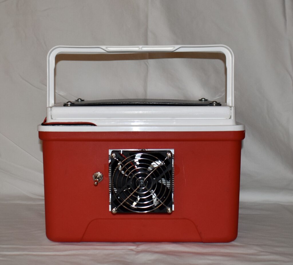

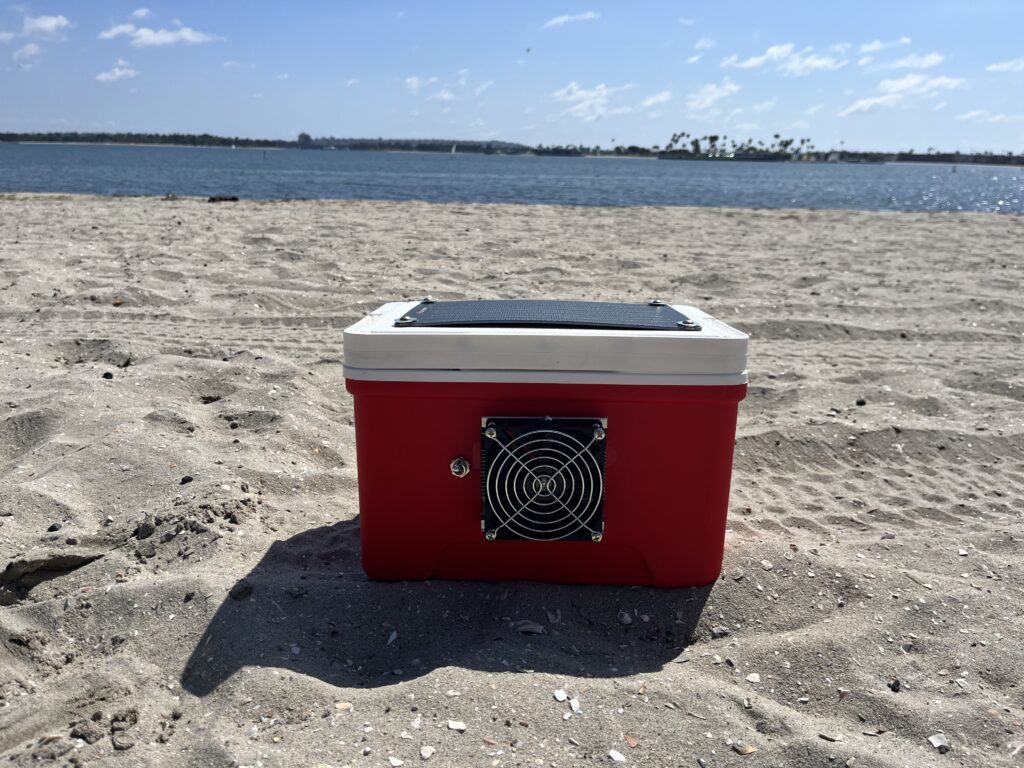
Isn’t she sexy?
Overview
After seeing that I could buy a basic battery powered refridgeration unit, I had the idea to build a battery powered cooler. A battery powered cooler is not a novel idea. In fact, Igloo has there own battery powered cooler. Furthermore, in the Amazon review section for the refrigeration unit, I found a DIY builder who had the same plan to use the unit in a styrofoam cooler. My gimmick was to avoid paying $400 for the Igloo cooler, but make my own that was more durable and asthetically pleasing than a janky styrofoam contraption Here’s what is in the picture:
| Part | Quantity | Total Cost | Link |
| Igloo 9 QT Laguna Ice Chest | 1 | 13 | Cooler |
| 12V Thermoelectric Peltier Refrigeration Cooling System | 1 | 19 | Fridge |
| 12V 6W Solar Panel | 1 | 20 | Solar Panel |
| 12V 30A Toggle Switch | 1 | 4 | Switch |
| Screws / Washers | 4 | 0 | Found in my junk drawer |
| $56 |
Now, I spent WAYYY more than $56 to assemble this device. First, I didn’t think through the physical dimensions of my cooler and at first bought a solar panel that was too long. Also, pleae consider that I did not own a soldering iron, voltmeter, or rotary tool and had to purchase all this equipment (but am very pleased that I now have all at my disposal). Despite spending over $300 (good lord) to build this, it was a wonderful way to pass the time.
Construction
Beyond my experience designing a horribly wobbly stool and a surprisingly elegant hat rack in the Hingham Middle School wood shop, this was a novel experience planning out how to build a physical device. Thus I started with what I know best, the electrical circuit. Before laying my hands on any cooler, I first bought and tested all the electrical equipment, being the battery, solar panel, and refrigeration unit.
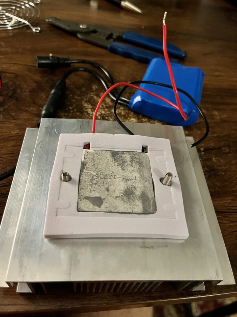
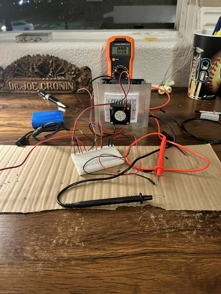
First, I connected the battery and refrigeration unit (henceforth referred to as fridge) and successfully powered both fans and Pelletier plate. Without the solar panel, the system ran for 36 minutes. Then I introduced the solar panel. The panel itself is rather useless, it is unable to charge the battery and only produces enough power to turn on the smaller of the two fans. However, I kept the solar panel because when running in parallel with the battery, I found that it improved the duration the system could run from 36 minutes to 42 minutes by sharing the load, when placed in full sunlight. This matched my estimate from the components specifications:
| Component | Voltage (v) | Current (i) | Energy (Wh) |
| Battery | 12v | 30 | |
| Fan (small) | 12v | 0.12 | 1.44 |
| Fan (large) | 12v | 0.3 | 3.6 |
| Pelletier plate | 12v | 4.5 | 54 |
| ~60 |
With Just the battery, the stored energy of 30Wh should power the cooling system for 30min (which is an underestimate of the measured 36 minutes). Adding the solar pannel in that produces 10W should reduce the load on the battery to 50W and thus a 30Wh battery should run for approximately 33.33 minutes. I am not sure how the battery and solar panel were able to run for 42 minutes, this could be because the battery was modestly rated, or the cooling system was drawing less power than the given specifications. I’m not complaining.
Once the electronics were tested (although after assembling I realized this was an underwhelming amount of testing), I began to think about the structure of the cooler. Originally, I wanted a small lunchbox size cooler. The 5 QT version of the Laguna Ice Chest was very appealing. However, I couldn’t find a solar panel small enough to attach to the top of the the device , so I pivoted to the slightly larger 9 QT model.
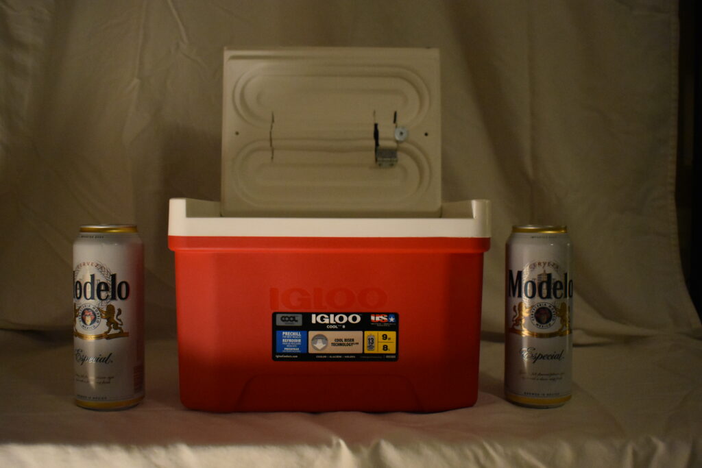
The way the igloo coolera are built is this, there is the inner chamber which is a smooth white platic. The cooler walls are an inch thick, the outer wall a corse red plastic, and inbetween the innner chamber and outer was is a sealed layer of insulating foam. The caveat is that the top of the cooler is hollow, although, it is asymetrically shapped with a design of both hollow coridors with two solid troughs.
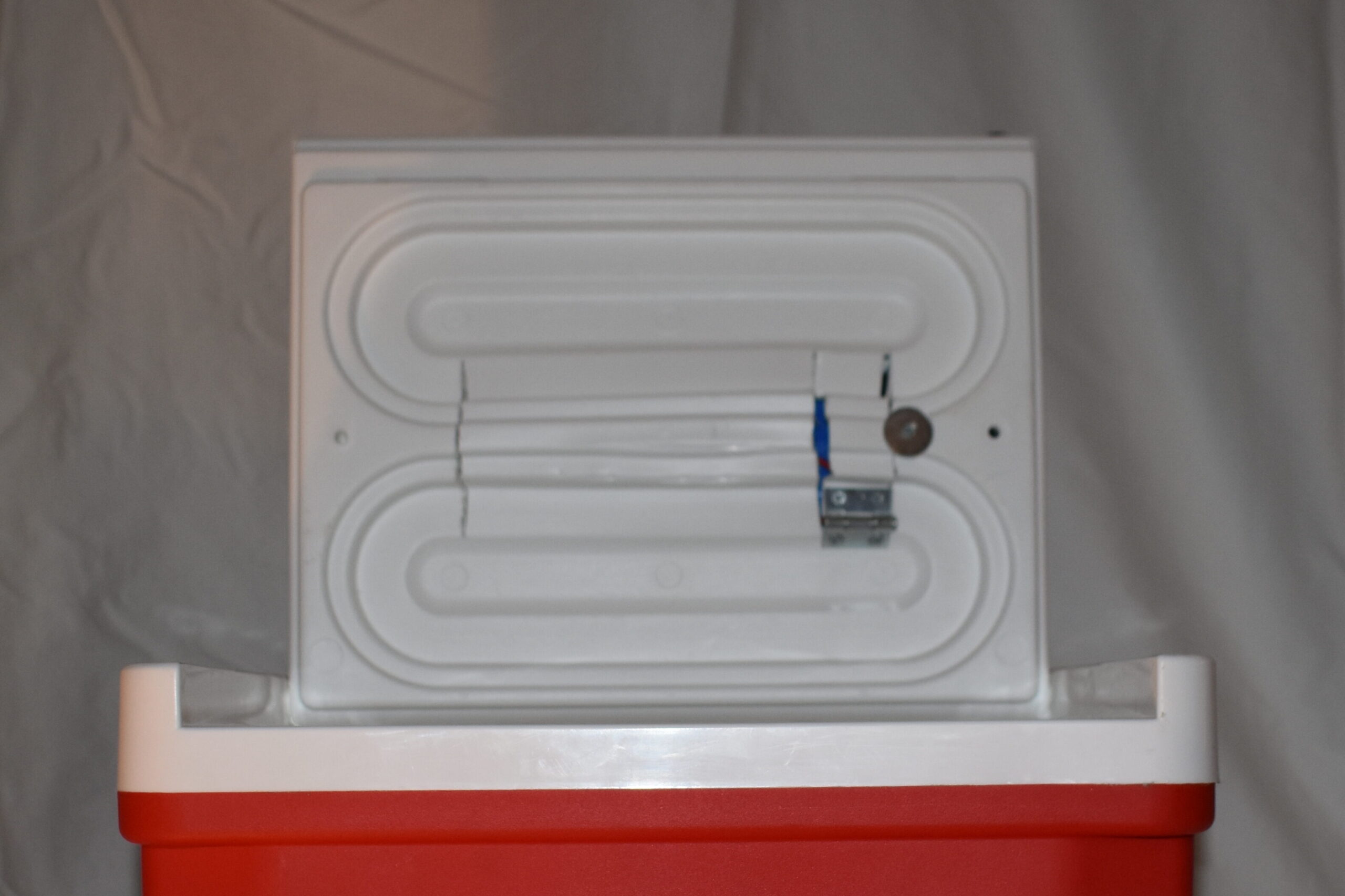
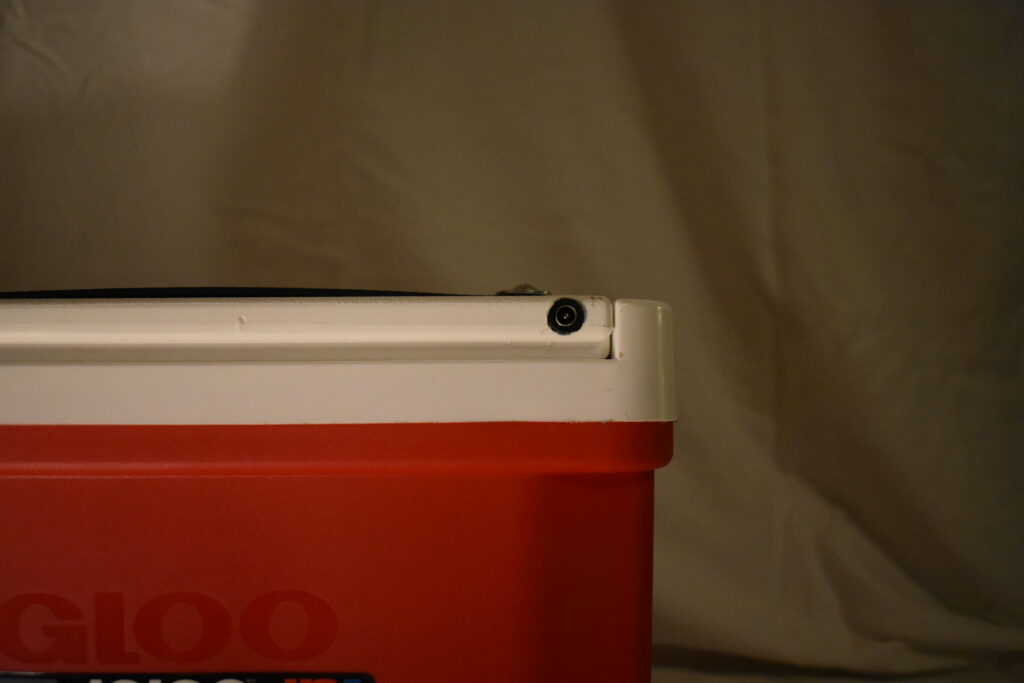
I went about exploiting the open corridors of the top as a polace to store the battery. Originally, I hoped the plastic was thin enough to be bent to allow the battery to slide into a cut in the roof. However, I found the plastic extremely resilient, resilience is an admirable trait unless one is resilient towards a lackluster ideal. A drug addict maintains amazing resilience in their commitment to consuming drugs despite the efforts of their family to prevent such behavior. Thus, I needed to coax the plastic out of its original form by applying my Genesis Dual Power heat gun. Then I was able to pull the plastic into a more open cavern for the battery. With a place for the battery, I then drilled a hole and threaded the battery charger port into the hole. Holding it in place with a ring of super glue.
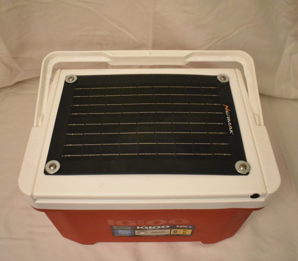
At this point, I was able to attach the solar panel to the top of the cooler. Allthis required were screws and washers to hold the solar pannel in place.
Now I had to figure out getting power from the battery stored in the top to the fridge that was going to be imbedded in the side of the cooler. The top detaches from the body of the cooler at the hinges. The hinges are just two plastic nubs that pop into ports on the body, similar to my plastic Oakley sunglasses. I appreciate this about my oakley sunglasses, I feel comfortable throwing them into my backpack as I know the arms of the glasses will detach before the glasses can break. Exploiting this design, I drilled a whole into the one of the nubs and one of the receiving port and was able to pass the power wires out of the top and along the side of the cooler body.
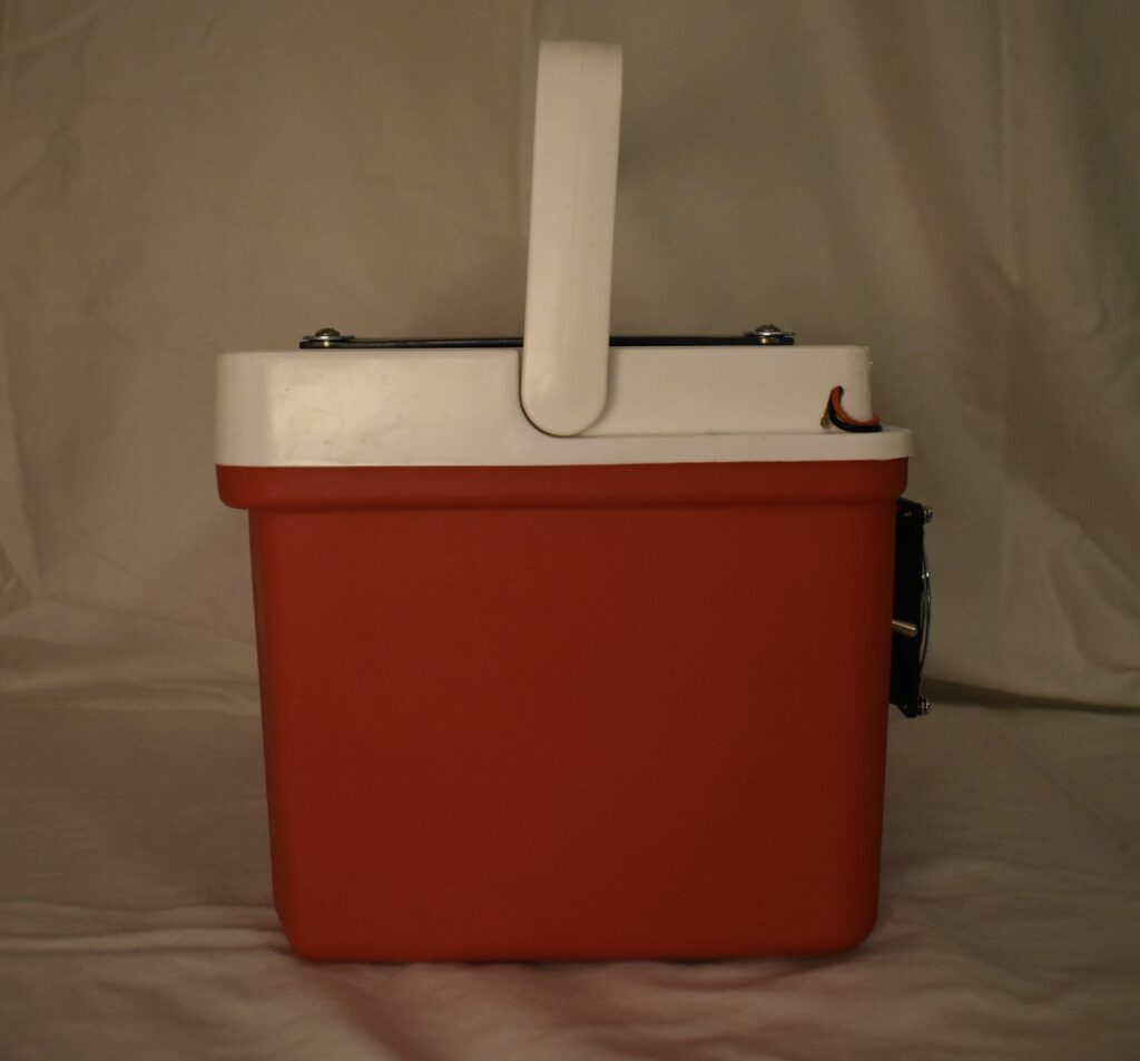
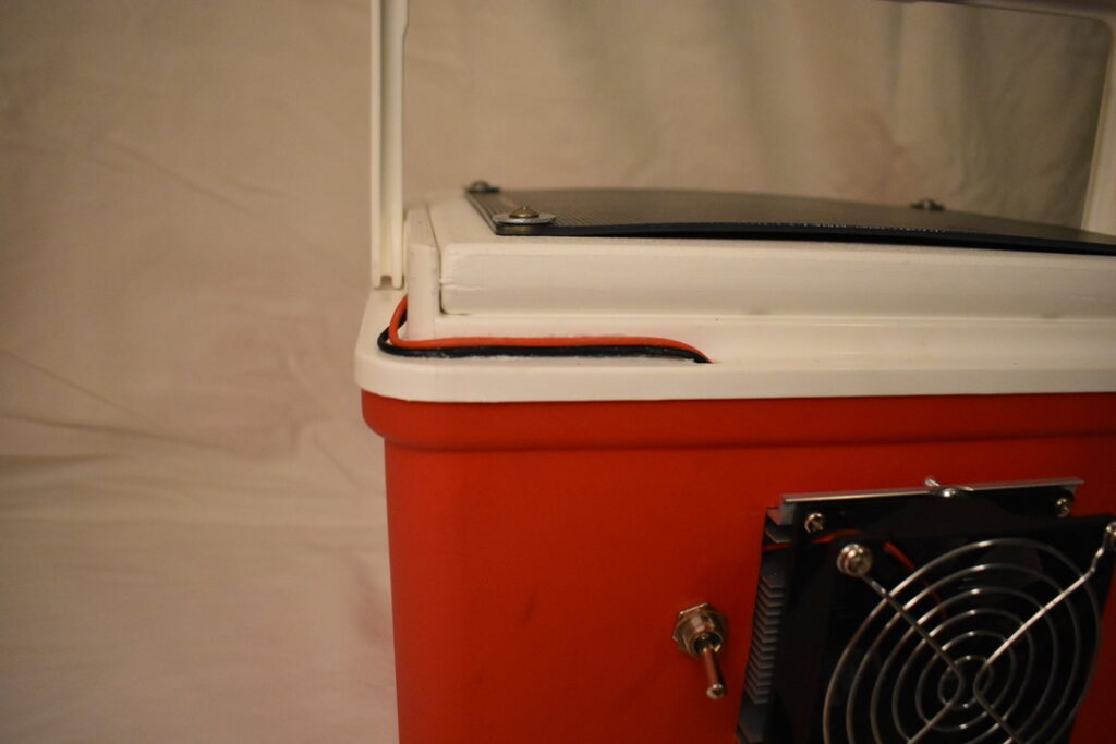
TA-DA!
With the top done, I could focus on installing the fridge.
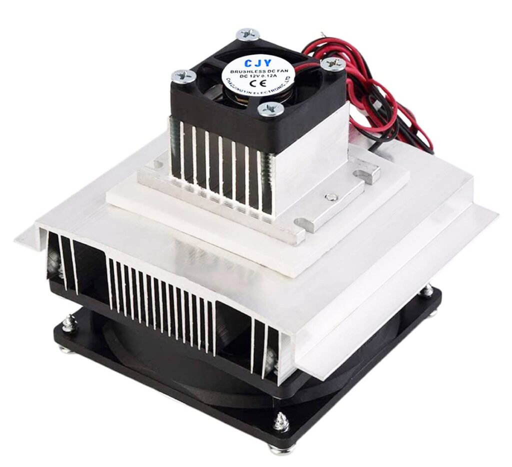
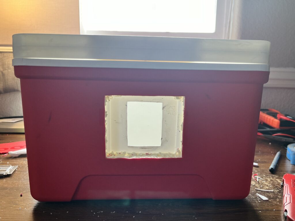
Knowing the thickness of the cooler it was my plan that the small fan and heat sink would intrude into the inner chamber, while the large heat sink and fan would be embedded and stick out of the cooler. So using a Dremmel, I cut into the outer shell of the cooler and insulating foam. Then I was able to mark on the outward facing side of the inner chamber where the small fan and heat sink would penetrate, then make an incision with a box cutter on the soft inner chamber plastic resulting in:
In order to minimize the footprint of the fridge, I used a metal cutting attachment to clip the wings on the large aluminum heat sink. The Dremel is a remarkably versatile tool, but it lacks power and it took a long time to cut off the excess aluminum, and I am fairly certain I breathed in a toxic amount of aluminum dust. I tried not to:

The last piece of distinct hardware to find a spot to install was the on/off switch. I decided to place it next to the fridge. It was almost to thick, but luckily I was able to clear out insulation and there was enough space to sandwich it between the inner chamber and outer shell. Threading the toggle of the switch through a drilled whole, all that was left to do was wire all the components together.
Because of the lack of space to play with, wiring everything together was a practice of finagling (soldering everything with my novice setup lead to the further intake of noxious gasses and burnt fingertips) but eventually I was able to connect all of the wires.
The final product:

Additional Notes
After polishing off the last task and giving the cooler a good wipe down, I was extremely pleased with how the cooler came out. It looks professional, the wiring is done well and seamlessly included in the design, and the refrigeration unit is operational. HOWEVER, it is not nearly as powerful as hoped. My initial test was to place two warm tall boy Modelos in the cooler and run the system until it ran out of juice. But when I opened the cooler it wasn’t very cold and the Modelos had hardly changed, they were noticeably cooler, but nothing compared to leaving them in a cooler full of ice.
I guess the purpose of this preliminary model is that the cooling system can serve as a supplement to a ice pack in the cooler, as it definitely lowered the internal temp of the cooler. In a secondary model I would include additional testing:
How long to charge battery?
Can I make it so the solar panel charges the battery?
Thermometer readings of the internal temp of the cooler?
Furthermore, ?I am now questioning the importance of a solar pannel, it does little to add to the total power of the cooler, and right now cannot charge the battery, would removing the solar pannel actually be beneficial? Considering that it was the most expensive component I am leaning towards no. Another feature I am considering adding is a secondary battery and refrigeration unit, this would undoubtably bolster the cooling power of the device. Finally, in a secondary model, I would significantly change my approach to utilizing the top of the cooler as a container. I would deconstruct the top further and then rebuild the top with custom plastic pieces that are more asthetically pleasing and allow for a more uniform and easily accessible space to install the batteries. I may even spray insulation into the top to improve the performance of the cooler and prevent the heat of the batteries from entering the inner chamber.
Guitar Hero
Kiryl Beliauski (kb3338), Patrick Cronin (pjc2192), & Dan Ivanovich (dmi2115)
CSEE 4840 at Columbia University, Spring 2024
Abstract
We recreated a level from Activision’s Guitar Hero, using their original controller hardware with our FPGA. Our project had four main components: 1) the guitar controller 2) VGA graphics 3) game logic/software 4) audio. While nowhere near as polished as the original game, we were able to reproduce the core gameplay for a single level. Unfortunately, difficulties with campus access meant we were unable to get the audio component fully working in time, but the final results of the other components are robust and complete. We made hardware modifications to the controller, designed and implemented custom hardware modules in Verilog for processing the controller input and outputting to VGA, custom kernel modules to communicate with these modules, game logic, a custom sprite-rendering system, and a small set of development tools to automate tedious parts of the development process. We even implemented a complete emulation system that allowed us to develop graphics and gameplay without access to the lab — the full game is completely playable in emulation.
Design Overview
Computer Hardware
INPUT
- Guitar Adapter Modding
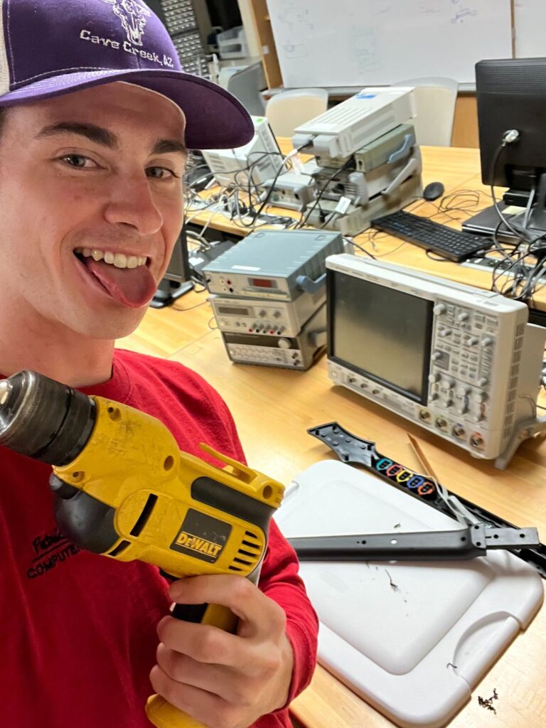
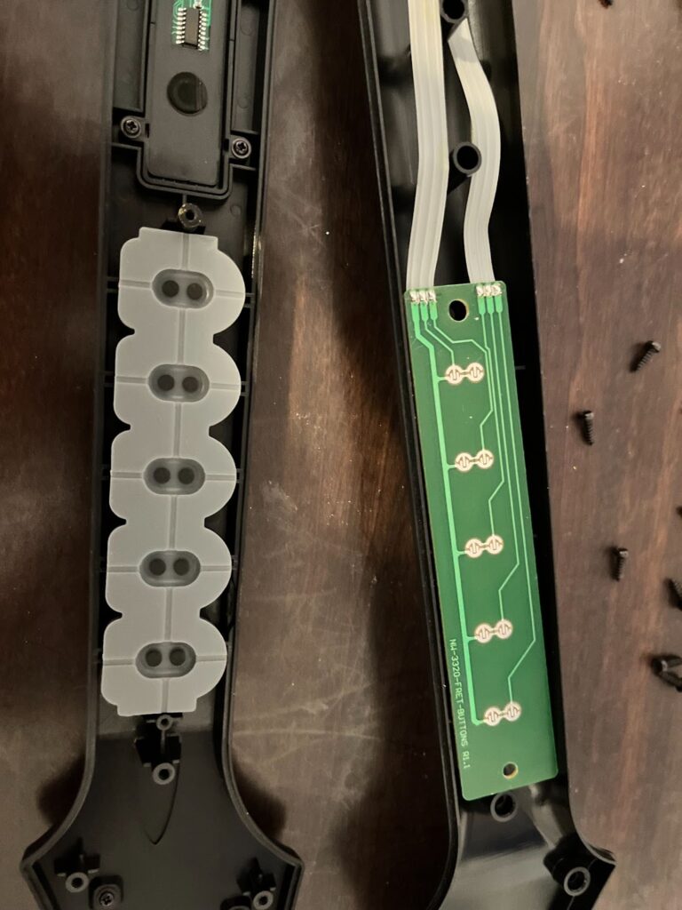
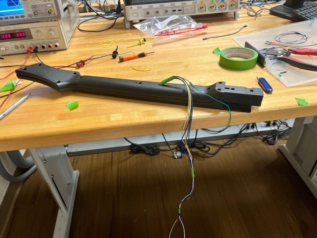
In order to create the controller we salvaged a vintage wii guitar hero controller. I then opened the controller and saw that the circuit was a very simple set of switches. When one of the colored buttons on the controller is pressed, the compression pushes down a metal piece that closes the circuit. After testing the functionality in the EE lab, I soldered wires to each of the note pins, and soldered an additional wire for the input power. Then, I drilled a hole in the guitar and threaded long wires out to be used as a connecting cable to the FPGA.
- Note Reader Hardware Module
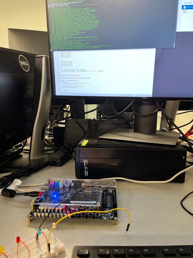
In order to send the signals from our guitar to the linux operating system we needed a hardware driver to interface with the avalon bus. The Wires carrying the input from the guitar controller are connected to GPIO pins on the FPGA. So the note reading module must read these inputs and send them to the avalon bus to be stored in memory. To design the hardware file, I started by creating a simple Verilog file that connects GPIO pins to the LEDR outputs, pictured below. I was able to successfully test my guitar inputs by seeing the lights change when I pressed the buttons, I was able to guarantee that the controller was working as expected. I then referenced the Avalon® Interface Specifications, and learned how to handle read requests coming from the avalon bus. When a read and chip select signal are read as inputs, the hardware module assigns the value of each of the 6 inputs from the guitar to the first 6 bits of the readata[7:0] signal. This readdata is read in by the avalon bus and then stored in a register file to be accessed by the software.
GRAPHICS
- VGA Framebuffer
I wanted as much of the graphics as possible to be handled by C, not Verilog, to avoid the long compilation times of lab 3. Thus, I decided to re-create the functionality of the DE1-SOC’s built-in /dev/fb0 device. In order to significantly reduce our usage of embedded memory, I made two major optimizations over /dev/fb0. First, only the 150-pixel-wide strip down the middle of the screen can be controlled by the framebuffer. All of the gameplay of the level itself occurs in 5 columns of notes, each of which is a 24 px by 24 px sprite. This meant 150 pixels of width was enough to draw 5 24-pixel-wide columns of notes, with 3 pixels of horizontal margin per column. Second, the R, G, and B values of each pixel are not directly stored in the framebuffer. Instead, each pixel is represented by a 6-bit number and explicitly mapped to an RGB value hard-coded in a switch statement used as a LUT. This supports a color palette of up to 64 colors, which ended up being more than enough for our project.
The VGA framebuffer takes in 32-bit writedata from the Avalon bus. As our memory module (see the VGA Memory section below) required a 17-bit address and the Avalon bus wouldn’t support an address of that width or a 6-bit writedata, I decided to combine the two into writedata. Thus, the VGA framebuffer ignores the address field and takes in 32-bit writedata of this format: {9 unused bits, 17-bit pixel number, 6-bit pixel data}. In every clock cycle, if the framebuffer is written to, the 6-bit pixel data value at writedata[5:0] is written into the memory module at address writedata[22:6]. In an always_comb block, if the current pixel falls within the 150-px wide strip, the 6-bit value stored at that pixel’s address in memory, pixel_data, is read from memory and an RGB output value is assigned based on the switch statement LUT.
- VGA Memory
The VGA memory module, vga_mem, is simply adapted from the Synchronous Memory module discussed in lecture. It takes 17-bit read/write addresses and takes/outputs 6-bit data. The memory itself is represented by logic [5:0] data[122775:0]. The rationale for 6-bit data was previously described — it gives us a 64-color palette. The addresses are 17 bits, as I just went with the simplest way of addressing a specific pixel: address = {pixel_y, pixel_x}, where pixel_y is a 9-bit value (our largest Y value, 479, is representable in 9 bits) and pixel_x is an 8-bit value (our largest X value, 149, is representable in 8 bits). This gives us a largest-possible address of {479 = 111011111, 149 = 10010101} = 11101111110010101 = 122773, which will fit in our data[122775:0].
Our total memory usage:
122776 chunks 6 bitschunks=92082 bits 92 kB
The original framebuffer’s memory usage:
(480 640) pixels 3Bytespixel=921600 Bytes 921 kB
This is a huge (10x) optimization over /dev/fb0
AUDIO
- CODEC
CODEC Data Flow
The CODEC of the board (WM8731) is configured using the I2C protocol. We have several VHDL files, specifically i2c.vhd, aud_gen.vhd, and audio_codec.vhd, which control several Altera IP blocks like PLL and the On-Chip Memory blocks. All of these blocks are then wrapped using a wrapper Audio Codec block that was made by us to ease the use of it with other modules of the whole project (like Patrick’s Note Reader Module).
I2C Protocol
The CODEC is configured in the following 3 ways:
- Slave mode. This allows our CODEC to receive all the necessary signals like main clock, interface clock, DAC synchronization, and actual audio data from the FPGA.
- USB mode. Here we set it up to use the frequency of 12MHz to generate a sample rate of 48 ks/s.
- PCM-mode audio interface. It is configured in the aud_gen.vhd file.
BLCK, DACLRC, DACDAT are provided by FPGA in Slave Mode
- Audio File
The audio file is stored on the on-chip memory, so it has to be preprocessed to be stored there efficiently. We use the Altera IP block for the on-chip memory and the required file format is MIF. To get the file from MP3 to MIF we first converted the file into a 16-bit mono PCM WAV file. After that, we have to strip everything from the file except the actual data, since the PCM data file has all the additional information at the beginning that we don’t need (bitrate, number of channels, file size, etc.). After that we convert the resulting data file into MIF format and its path is added to the Altera IP block.
Software
Software Structure:
game_logic.c
The most important file. This is the orchestrator that coordinates the input and output. First, the main thread processes the sprites, connects to our HW kernel modules, and parses the hard-coded notes for the level from a .txt file. The game then steps into a start screen menu, then the main gameplay loop, and finally an ending screen that checks for a high score.
guitar_state.c/h
Defines a struct that represents the state of the guitar, plus helper methods for processing the data from the Verilog module into this struct.
guitar_reader.c/h
An adapted version of the lab 3 VGA ball kernel module that communicates with our Verilog module for the guitar.
vga_framebuffer.c/h
An adapted version of the lab 3 VGA ball kernel module that communicates with our Verilog module for the VGA framebuffer.
sprites.c/h
Structs and helper methods to parse, store, and render a sprite from a PNG.
fbputchar.c/h
An adapted version of the lab 2 fbputchar code that works with our custom framebuffer and color palette.
colors.c/h
Defines structs and an enum for representing colors in our color palette.
generate_verilog_colors.py
A helper script that parses our color palette from colors.c and outputs the body of the Verilog switch statement used as a pixel_data LUT in vga_framebuffer.sv.
vga_emulator.c/h
Uses libsdl2-dev to emulate the VGA. Also uses the keyboard to emulate the guitar.
global_consts.h
Defines global constants about the VGA screen output.
song_data.h
Defines constants about the song, such as BPM and notes per measure. Also defines a struct to represent a note of rows on screen.
helpers.c/h
Defines miscellaneous helper methods.
high_score.txt
Stores the highest score (accuracy) a player has achieved on this level.
single_note_commaless.txt
A cleaned export of the CSV for our song, containing information about the notes in every row. game_logic.c automatically parses this file and plays those notes in the level.
Makefile
Defines two important targets: make all, which compiles all the files necessary to run game_logic, and make modules, which compiles all the kernel modules.
Custom Development Tools
Throughout this project, we also developed some custom tools to expedite or automate parts of the development process. For example, the generate_verilog_colors.py tool made it very easy to keep our color palettes synchronized across C and Verilog. When campus shut down, we also took the time to develop an emulation system in C using libsdl2-dev. Dan programmed a system that used the game_logic’s framebuffer in a SDL2 window to render the graphics, which allowed us to continue to develop sprite rendering without our FPGA or monitor. The system also uses the keyboard in place of the guitar, using the keys 1-5 in place of each button on the guitar and the spacebar in place of the strumbar. We were therefore able to develop the graphics and general game logic without physical lab access, and the system was designed robustly enough that, even after all the in-person development we did once campus re-opened, the emulator still worked and the final game can be played entirely in emulation. Just flip int EMULATING_VGA to 1 in the start of game_logic.c to enable emulation.
Results and Performance
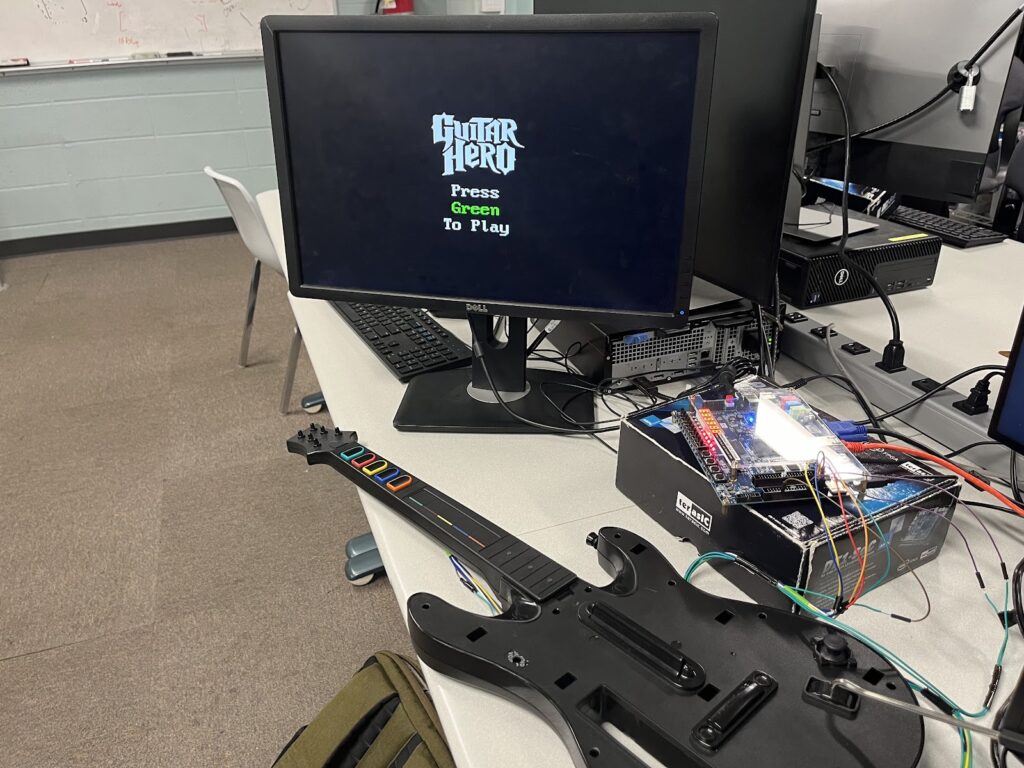
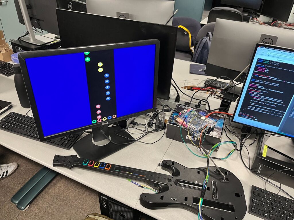
The final results of the game logic, VGA framebuffer, and guitar reader are robust and complete. We even implemented a complete emulation system that allowed us to develop graphics and gameplay without access to the lab — the full game is completely playable in emulation. The scoring algorithm is fairly accurate, but will sometimes fall victim to imperfect strum bar debouncing.
Ultimately, the VGA graphics could use some more optimizations to be smoother. Notably, we could redesign the framebuffer to take in the pixel data for chunks of 5 pixels at a time, and use the address to define the address of the first of these 5 pixels. This way, we could update the contents of the vga_mem module 5 times faster, which might help with smoothness.
The guitar itself could also use some fixing. This guitar is almost 15 years old and underwent several years of use before making its way to this project, and the strumbar was already partially broken (strumming down hardly works), which does notably reduce the rate at which you can comfortably play a rapid series of notes.
The audio part of the project was not successful. The issue was mainly in the fact that we could not set up the wrapper module to work with the other parts of the project (it worked in isolation).
Lessons Learned
Quartus
One of the most important skills we developed over the course of this project is our ability to use Quartus to develop a complete hardware project. Beginning the project, we had a slight introduction to Quartus in lab 3 but had no ability to handle it with agency to create a novel application. What was a learning experience was the need to read documentation slowly and thoroughly to understand how to use the software. After reading Intel user guides that TAs showed us, Quartus became much more manageable and an extremely useful tool.
Memory Efficiency
When writing software on our laptops, we don’t have to concern ourselves with memory efficiency anywhere near the extent to which we needed to in our Verilog modules, where every single bit counted. If we were to do this project again, we’d definitely focus even more on memory efficiency. For example, the VGA framebuffer’s current addressing leaves about ⅓ of its memory unused — a more complex addressing system could probably be designed that would reduce this inefficiency. As mentioned in the previous section, we could also have redesigned how writedata and address are used to have pushed data to the framebuffer 5x faster.
Planning Ahead
Another lesson learned was surrounding planning. Our original block diagram that we submitted for our design proposal lacked a lot of knowledge and research for future steps, especially in communicating with the guitar (which we had not yet obtained). We assumed that each hardware (visuals, controller, and audio) would be relatively simple, but struggled significantly with each. If We were to do a project like this again, we would have spent much more time thinking about what we need to learn before embarking out to build. We chose to build on the fly, and this was fine because the project was of small size, but with a bigger project, the lack of planning definitely would have shot us in the foot.
Frequency Meter
Patrick Cronin (Pjc2192), Evangelos Siokis (es4072)
Abstract
We created a digital frequency meter that determines the frequency of a 0 to 5V square wave produced by a function generator. To do this we first developed a timer using a 555 timer circuit that allowed us to tune a pulse to a specific duration. Then, by Nanding a one second timer pulse and the input signal (the signal we are looking to measure) we fed the output of the Nand gate to a counter circuit. The counter circuit incremented a 8 bit digital display every time it received a positive pulse. Thus the counter tallied the number of oscillations of the input signal over a one second period to determine the frequency of the signal.
555 Timer
The First step was to produce a pulse that lasted exactly one second.
To implement this we decided to use a Texas Instrument LM555 timer chip. “The 555 Timer chip is a ‘standard’ MSI component that finds a wide range of applications in analog-digital interfaces. While, strictly speaking, this is a linear (analog) IC, it is widely used in digital systems. The basic structure of the 555 chip is shown in Fig. 1. Both TTL and CMOS versions of this chip are commercially available. The basic timer circuit consists of two voltage comparators, an SR latch, and a discharge transistor.” (E3082 )
Here is our wired 555 Timer as an oscillator, following the schematic in Fig. 2 :
We wired the 555 chip into its “monostable” mode using a resistor and capacitor. We found that the stable mode could be set to either 5v or 0v, depending on whether or not the trigger was continually on and pulsing low, or continually off and pulsing high.
We realized we wanted to have physical control over starting the timed pulse. A button we could press that started the pulse. So we built a debounced button and connected the 555 trigger to a debouncer circuit.
Debouncer Circuit
Our debouncer circuit:

The debouncer in figure 4 cleverly utilizes nand gates in order to stabilize (debounce) the output as the connection of the pushbutton switch changes. Here, if the switch points to the R node, the R node becomes grounded and the top input to the nand gate becomes 0. Without knowing the top nand gates bottom input we already know that the output will be 1. Thus the top input of the bottom nand gate is now 1, the bottom input of the bottom nand gate is connected to the voltage source, thus it receives two 1s and outputs a zero. This zero output from the second nand ate is fed back into the top nand gate. When the switch moves from one terminal to the other, the connection is broken for a brief but possibly destabilizing moment. However, because the bottom nand gate continues to output a 0, the top nand gate will continue to output a 1 maintaining the same output while the switch changes. Thus the only change occurs when the switch has established contact with the second terminal
Returning to timer …
Then we connected our debounced push button output to the trigger of the 555 timer circuit. This provided a clean starting signal for the timed pulse. We then introduced a time constant to the 555 circuit by inducing a resistor and capacitor in series as shown below.
We estimated that megacoulomb capacitor and microfarad resistor would produce a one second time constant and thus one second pulse because during this period the 555 receives a signal large enough to turn it on. However, when we began to measure the pulse duration, we found a discrepancy.
Tolerance:(( texperimental – ttheoritical) / ttheoretical ) x 100% = ((1.15 – 1)/1) x 100% = 15%> 10%
Our guess was 15% off which was not within a 10% tolerance. This may have been due to the use of the debouncer circuit as a trigger. While we try to provide a trigger from the debouncer that is of a negligible duration, the time the trigger is pressed may not be negligible. If I held down the trigger, the pulse would continue to stay on. So when I press the trigger to initiate a pulse, I may have held it down for a hundredth of a second too long causing our pulse to be slightly longer than 1 second.
In order to control the time on we had to introduce a potentiometer in series with the resistor in order to fine tune the resistance–>fine tune the time constant. Leaving us with the final timer schematic:

Implemented:
Pulse received:
We then realized that if we knew the duration of the pulse, we could then use a counter to tally the number of periods that pass during a given pulse period. After we realized this, we understood we could use the debouncer, 555 timer, and a counter circuit in conjunction with a and gate to count pulses during a given period.
To create an and gatewe took a nand gate chip and wired the output of one nand gate into both the outputs of another nand gate, creating the logically equivalent and gate. Above, we explained how to use a capacitor and resistor to generate a pulse of one second using the 555 chip. We fed the one second pulse into one input of our and gate. Into the other input we fed the square wave signal we wanted to measure the frequency of. Now, when we pressed the trigger to start the one second pulse the and gate produced an output during that one second while the pulse peaked. Thus, the number of positive outputs from the and gate was the number of cycles a signal completed during a one second interval. The output of our and gate we fed into a counter circuit.
Counter Circuit
A Counter circuit was built using a Fairchild 74ACT161 Synchronous Presettable Binary Counter, a Texas Instrument Binary to 7 segment Latch Decoder chip, and a 7 segment display.
This circuit was tested using the debouncer push button. Each time the pushbutton was pressed the counter chip incremented, the decoder translated the signal, and the hex display updated its value by one.
Putting It All Together!
The Debounced push button, timer circuit, and gate, and counter circuit were then all wired together. Before we hit the trigger to the whole circuit, to begin the pulse, the counter was reset to 0. When the pulse began, every time the input signal produced a new peak of the counter was incremented by one. Thus, we created a circuit that counts the number of cycles during a given time period. Knowing that the period was one second and the number of cycles during that period, the frequency was just 1/# of cycles. Conveniently, we chose the time period to be one second, so the number the counter displays is actually in cycles per second or Hertz.
Pulse provided:
Output received from and gate:
Full circuit:
Home Automation

Hardware
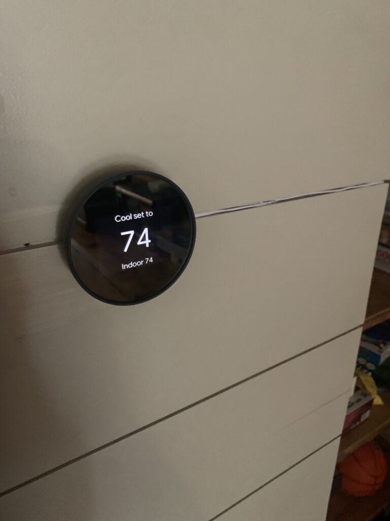
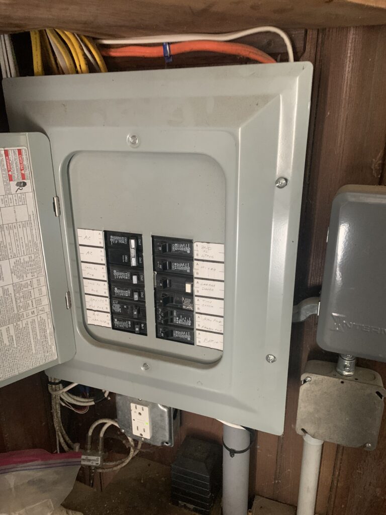
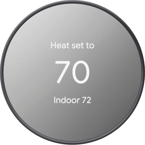
In order to address my families exorbitant electrical bill I decided to automate our home and install a nest thermostat.
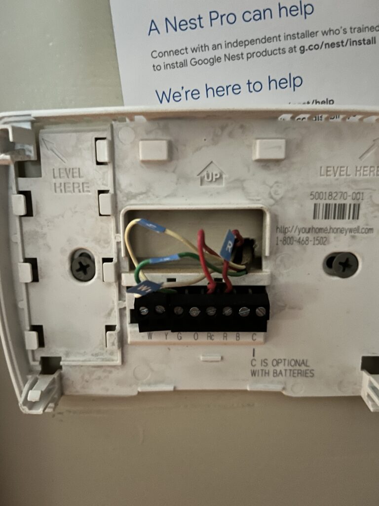
The instillation proved challenging, as we live in an old house, our AC unit is uniquely wired, and the nonstandard wiring system caused some issues. First, I shut off power at the breaker box. Then I removed the current thermostat to disconect it from the HVAC wiring.
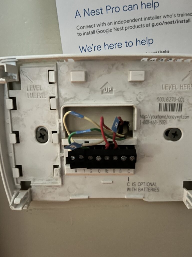
From the picture one can see that their is a Y, G, R, and w1 wires (the R and Rc connections are shorted together). Generally the wires are:
White (W): Connects to the heating system
Yellow (Y): Connects to the air conditioning compressor
Green (G): Connects to the fan
Red (Rc or Rh): Connects to the power source
Blue or black (C): Connects to 24-volt power to the thermostat
Orange: Connects to the heat pump
Noticeably there is no C wire in the diagram, meaning that the thermostat had no direct power source. However, I hoped that the Rc wire would be able to provide power to the thermostat. The wires were tagged and then installed in their corresponding ports on the nest thermostat. The thermostat acknowleged connection but issued a warning, E262, in refrence to a lack of a C wire.
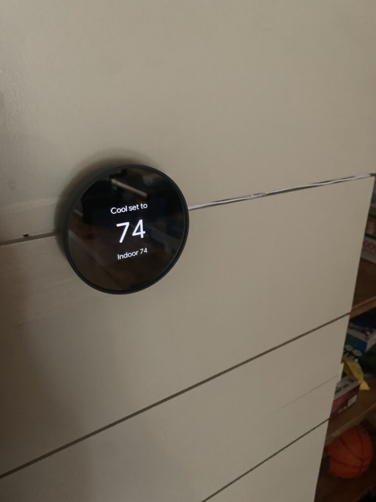
There are a few possible solutions to divert power to the Nest thermostat. Instead of messing with the HVAC wiring, I decided it would be easier to buy a 24v power adapter that plugs into the wall outlet. After wiring in the power connection the error went away and I could begin connecting to the Google smart home app. Even though I would prefer to not have a seperate power supply, I was able to hide the chord and the instillation came out well.
Raspberry Pi
While I could have just connected to the google cloud smart home application, I wanted a more customized control system. Home Assistant is an amazing open source software solution. Home Assistant would allow me play music on my homes sonos system, monitor our solar panels, and control wifi connected lightbulbs in my room all from a singular control board in the home assistant app.
Home Assistant requires a dedicated server as to continually monitor the home system. To create a cheap server, I bought a Raspberry Pi 3+ and flashed the home assistant image onto it. To integrate the server into our home network, I connected it to a router using a Cat 8 Ethernet cable. Here is a picture of the server:
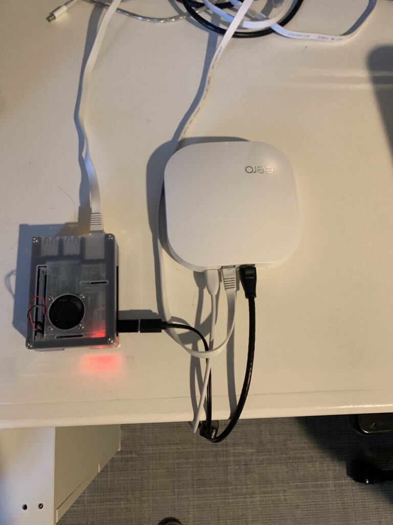
A side note is that I installed a fan to help cool the Raspberry Pi as it will be constantly running and the fan was less than $5.
Google API
Most smart devices talk directly to Home Assistant. However, Google devices must talk to the google smart home software. Thus, to integrate them into Home Assistant I had to instantiate an API between Home Assistant and the Google Cloud in the google cloud console. I opened created a specific project, enabled the smart home API, and checked the boxes on network security to enable communication with home assistant.

Let me emphasize that while I do not have documentation of the debugging that had to be done, this API process was not easy. I suspect Google does not want you to use outsider software with its home automation devices. However, eventually I was able to successfully connect into home assistant. Here is a picture of my dashboard.
Automation
Once I had home assistant up and running and my nest device connected to home assistant I could begin automating control of my house. Home assistant offers the abilities to upload .yaml files for configuring automation, or user friendly conditional blocks to for basic automation. My goal of installing a nest thermostat was to reduce the AC in the back half of our house where the garage, dining room, and guest room are. While this AC zone is used consistently, it is used much less than the front of the house but is constantly left running at full blast because people forget to turnback down the AC when they finish using the space. Thus I just wanted to make sure that the AC was turned off at the end of the day every day as to make sure the AC is not left running to no end. I also wanted to have the room set to higher than normal temp in the mornings (around 76 degrees) so that when the AC is put on full blast it doesn’t take an unreasonable time to cool, and preventing the back half from getting overly hot and beginning to strain the AC system cooling the front half of the house. In an ideal world I would have installed another NEST thermostat on the front half of the house, but the homeowners (my parents) drew a line in the sand preventing me from touching the main AC zone.
Conclusion
All in all the project was a success, I was able to successfully create a smart home dashboard for our house plus install an automated AC thermostat to reduce our energy usage.
Autonomous Vehicle
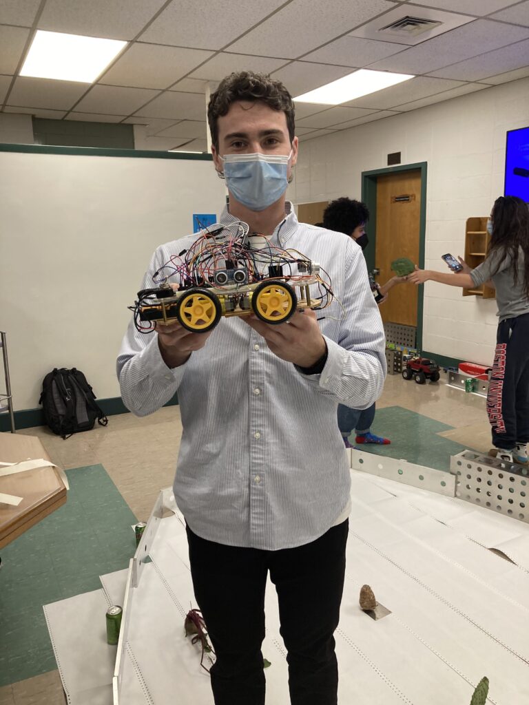
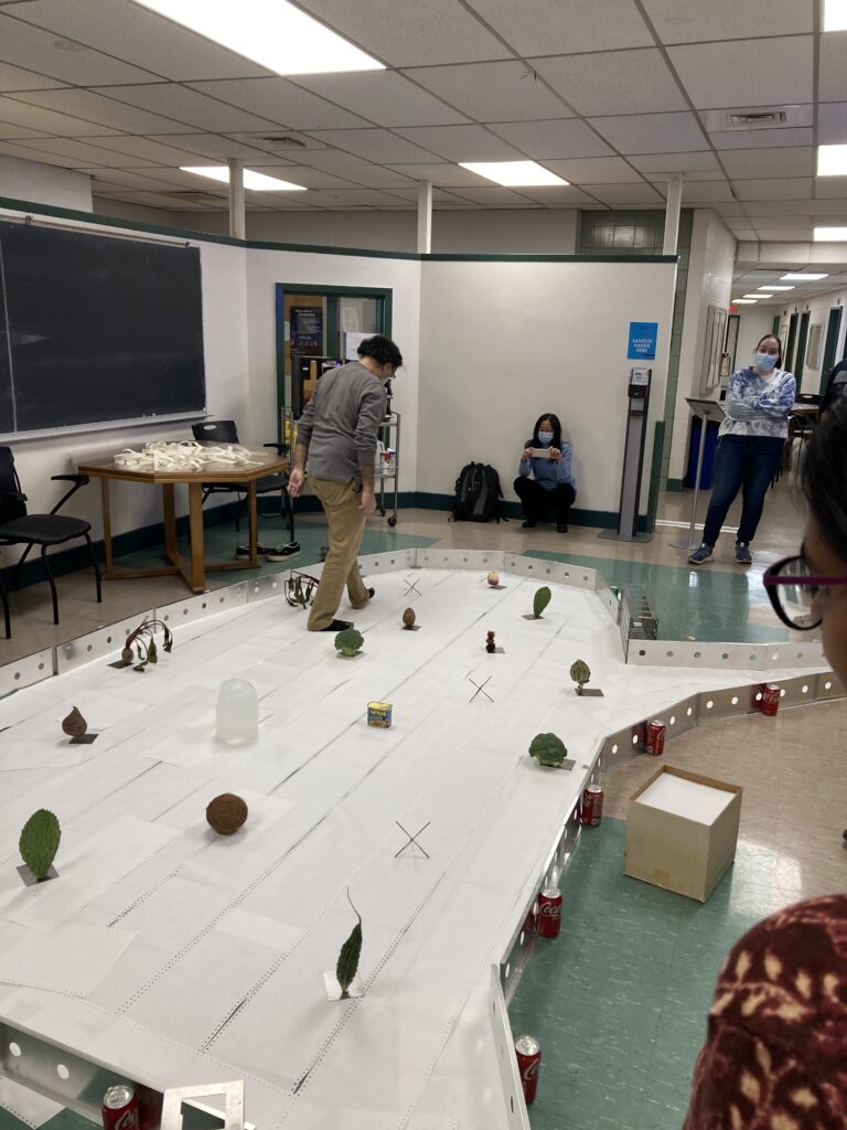
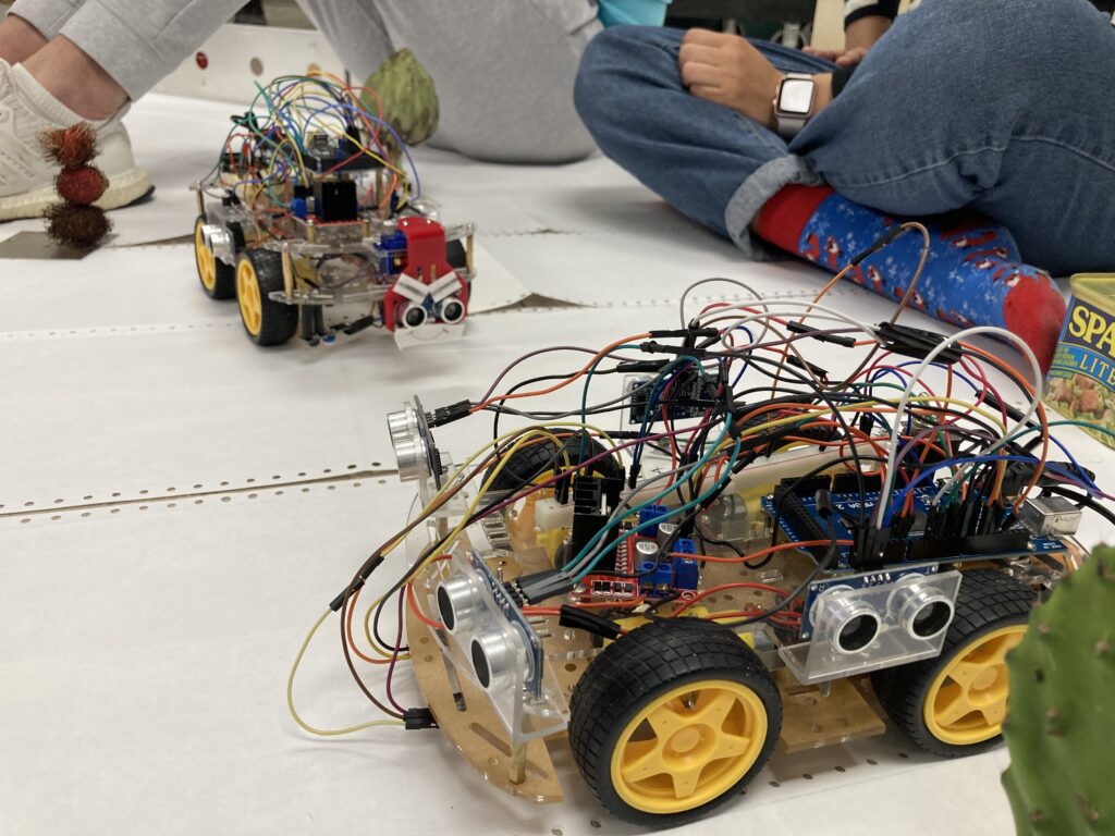
While in my final year at Georgetown I was part of a team of undergrads and PHD students that built an autonomous vehicle to navigate an obstacle course. We were given a chassis with 4 actuated motors, an Arduino, and a selection of sensors at our disposal. We had full autonomy to design and implement a vehicle that navigated a series of obstacles.
Hardware: Arduino, ultra sonic distance sensors, and photo detectors.
Software: Arduino Programming Language (APL).
Obstacles: Follow a dotted line, drive through a tunnel, navigate a chaotic obstacle course.
Ankangmassage.com
Please check out the website I created for a local small business: AnkangMassage
