
Kiryl Beliauski (kb3338), Patrick Cronin (pjc2192), & Dan Ivanovich (dmi2115)
CSEE 4840 at Columbia University, Spring 2024
Abstract
We recreated a level from Activision’s Guitar Hero, using their original controller hardware with our FPGA. Our project had four main components: 1) the guitar controller 2) VGA graphics 3) game logic/software 4) audio. While nowhere near as polished as the original game, we were able to reproduce the core gameplay for a single level. Unfortunately, difficulties with campus access meant we were unable to get the audio component fully working in time, but the final results of the other components are robust and complete. We made hardware modifications to the controller, designed and implemented custom hardware modules in Verilog for processing the controller input and outputting to VGA, custom kernel modules to communicate with these modules, game logic, a custom sprite-rendering system, and a small set of development tools to automate tedious parts of the development process. We even implemented a complete emulation system that allowed us to develop graphics and gameplay without access to the lab — the full game is completely playable in emulation.
Design Overview
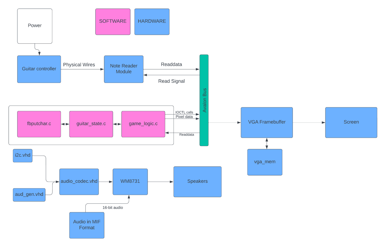
Computer Hardware
INPUT
- Guitar Adapter Modding
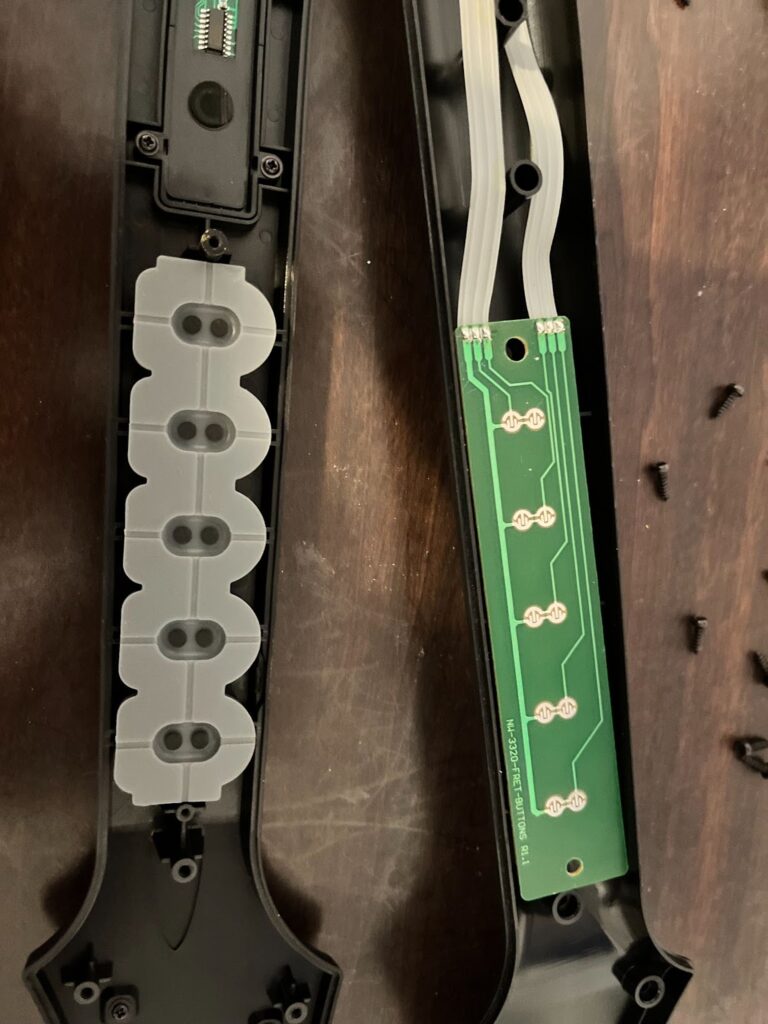
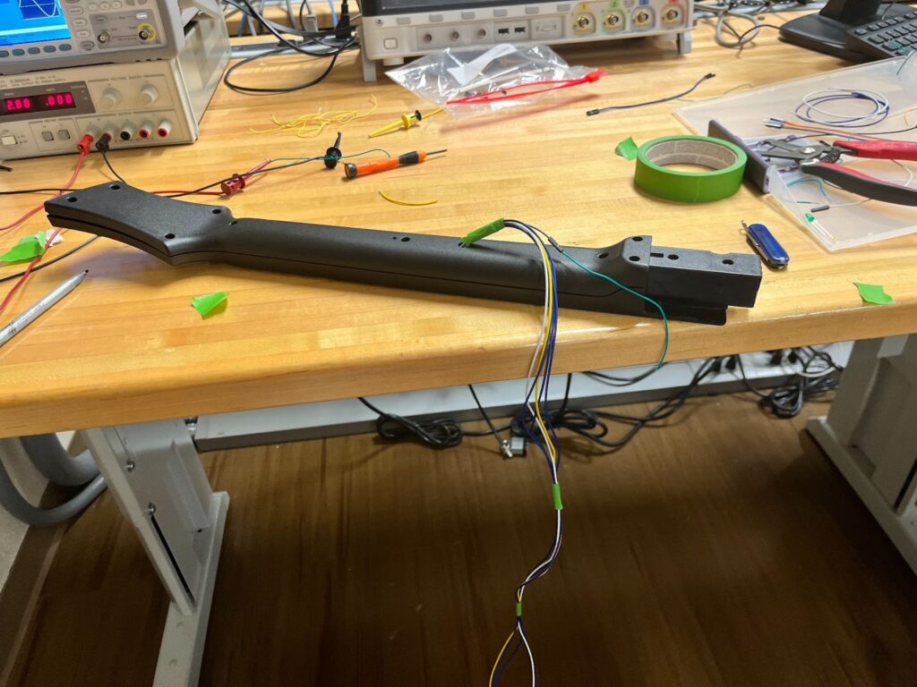
In order to create the controller we salvaged a vintage wii guitar hero controller. I then opened the controller and saw that the circuit was a very simple set of switches. When one of the colored buttons on the controller is pressed, the compression pushes down a metal piece that closes the circuit. After testing the functionality in the EE lab, I soldered wires to each of the note pins, and soldered an additional wire for the input power. Then, I drilled a hole in the guitar and threaded long wires out to be used as a connecting cable to the FPGA.
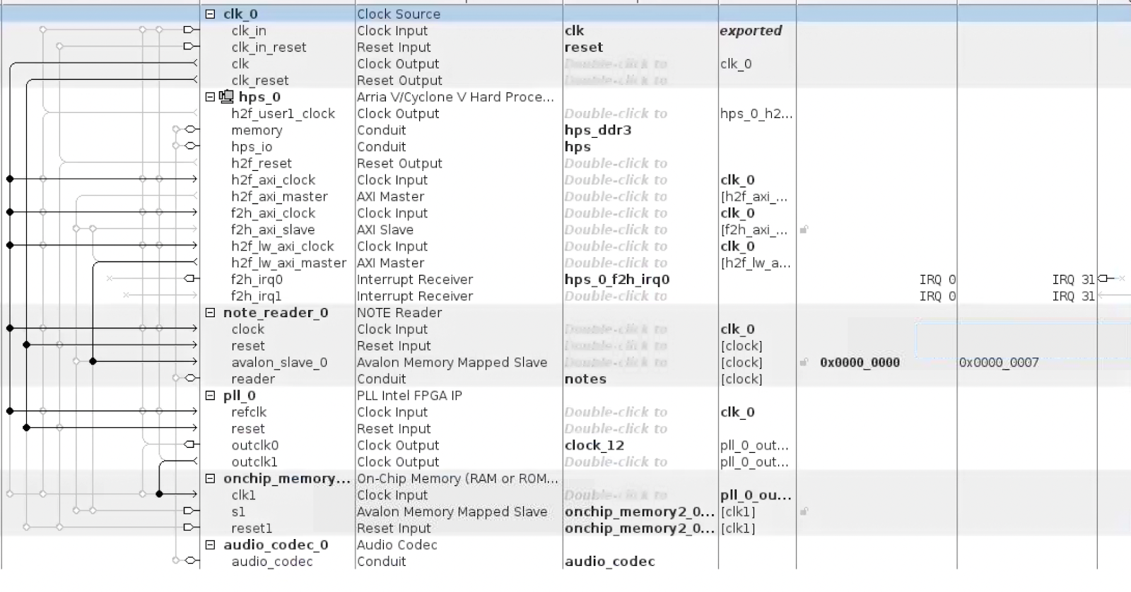
- Note Reader Hardware Module
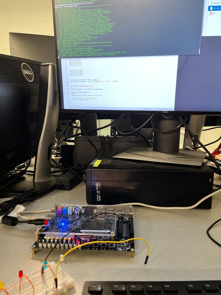
In order to send the signals from our guitar to the linux operating system we needed a hardware driver to interface with the avalon bus. The Wires carrying the input from the guitar controller are connected to GPIO pins on the FPGA. So the note reading module must read these inputs and send them to the avalon bus to be stored in memory. To design the hardware file, I started by creating a simple Verilog file that connects GPIO pins to the LEDR outputs, pictured below. I was able to successfully test my guitar inputs by seeing the lights change when I pressed the buttons, I was able to guarantee that the controller was working as expected. I then referenced the Avalon® Interface Specifications, and learned how to handle read requests coming from the avalon bus. When a read and chip select signal are read as inputs, the hardware module assigns the value of each of the 6 inputs from the guitar to the first 6 bits of the readata[7:0] signal. This readdata is read in by the avalon bus and then stored in a register file to be accessed by the software.
GRAPHICS
- VGA Framebuffer
I wanted as much of the graphics as possible to be handled by C, not Verilog, to avoid the long compilation times of lab 3. Thus, I decided to re-create the functionality of the DE1-SOC’s built-in /dev/fb0 device. In order to significantly reduce our usage of embedded memory, I made two major optimizations over /dev/fb0. First, only the 150-pixel-wide strip down the middle of the screen can be controlled by the framebuffer. All of the gameplay of the level itself occurs in 5 columns of notes, each of which is a 24 px by 24 px sprite. This meant 150 pixels of width was enough to draw 5 24-pixel-wide columns of notes, with 3 pixels of horizontal margin per column. Second, the R, G, and B values of each pixel are not directly stored in the framebuffer. Instead, each pixel is represented by a 6-bit number and explicitly mapped to an RGB value hard-coded in a switch statement used as a LUT. This supports a color palette of up to 64 colors, which ended up being more than enough for our project.
The VGA framebuffer takes in 32-bit writedata from the Avalon bus. As our memory module (see the VGA Memory section below) required a 17-bit address and the Avalon bus wouldn’t support an address of that width or a 6-bit writedata, I decided to combine the two into writedata. Thus, the VGA framebuffer ignores the address field and takes in 32-bit writedata of this format: {9 unused bits, 17-bit pixel number, 6-bit pixel data}. In every clock cycle, if the framebuffer is written to, the 6-bit pixel data value at writedata[5:0] is written into the memory module at address writedata[22:6]. In an always_comb block, if the current pixel falls within the 150-px wide strip, the 6-bit value stored at that pixel’s address in memory, pixel_data, is read from memory and an RGB output value is assigned based on the switch statement LUT.
- VGA Memory
The VGA memory module, vga_mem, is simply adapted from the Synchronous Memory module discussed in lecture. It takes 17-bit read/write addresses and takes/outputs 6-bit data. The memory itself is represented by logic [5:0] data[122775:0]. The rationale for 6-bit data was previously described — it gives us a 64-color palette. The addresses are 17 bits, as I just went with the simplest way of addressing a specific pixel: address = {pixel_y, pixel_x}, where pixel_y is a 9-bit value (our largest Y value, 479, is representable in 9 bits) and pixel_x is an 8-bit value (our largest X value, 149, is representable in 8 bits). This gives us a largest-possible address of {479 = 111011111, 149 = 10010101} = 11101111110010101 = 122773, which will fit in our data[122775:0].
Our total memory usage:
122776 chunks 6 bitschunks=92082 bits 92 kB
The original framebuffer’s memory usage:
(480 640) pixels 3Bytespixel=921600 Bytes 921 kB
This is a huge (10x) optimization over /dev/fb0
AUDIO
- CODEC
CODEC Data Flow
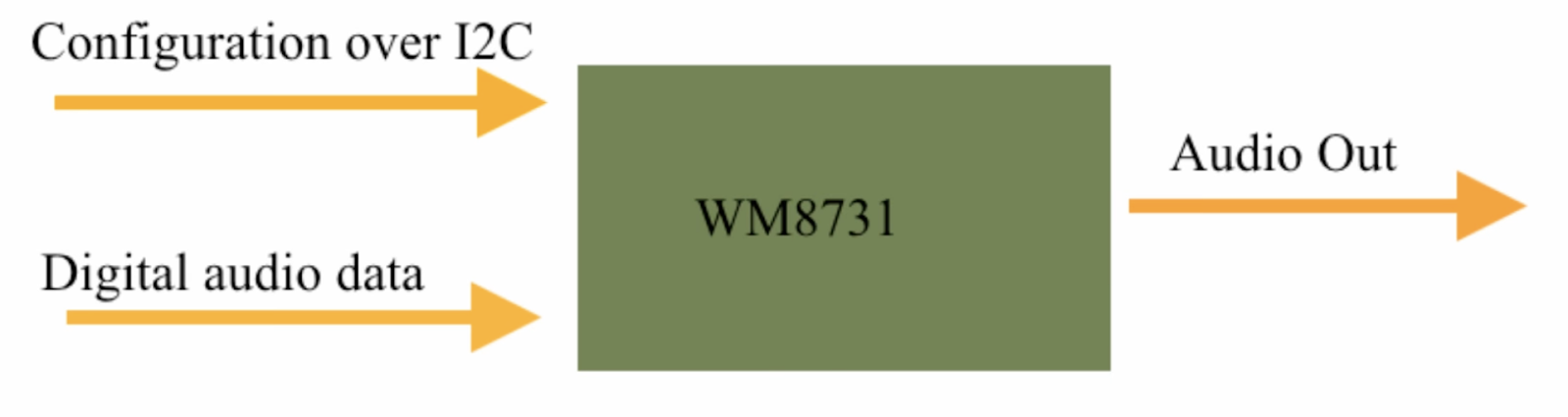
The CODEC of the board (WM8731) is configured using the I2C protocol. We have several VHDL files, specifically i2c.vhd, aud_gen.vhd, and audio_codec.vhd, which control several Altera IP blocks like PLL and the On-Chip Memory blocks. All of these blocks are then wrapped using a wrapper Audio Codec block that was made by us to ease the use of it with other modules of the whole project (like Patrick’s Note Reader Module).
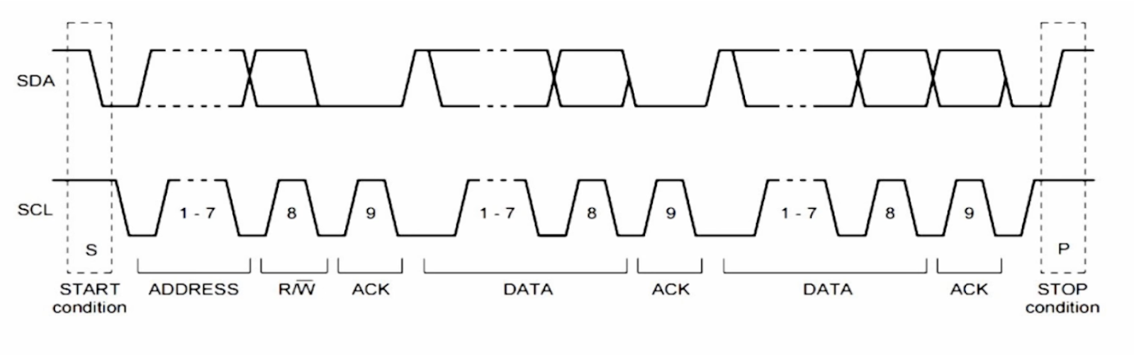
I2C Protocol
The CODEC is configured in the following 3 ways:
- Slave mode. This allows our CODEC to receive all the necessary signals like main clock, interface clock, DAC synchronization, and actual audio data from the FPGA.
- USB mode. Here we set it up to use the frequency of 12MHz to generate a sample rate of 48 ks/s.
- PCM-mode audio interface. It is configured in the aud_gen.vhd file.
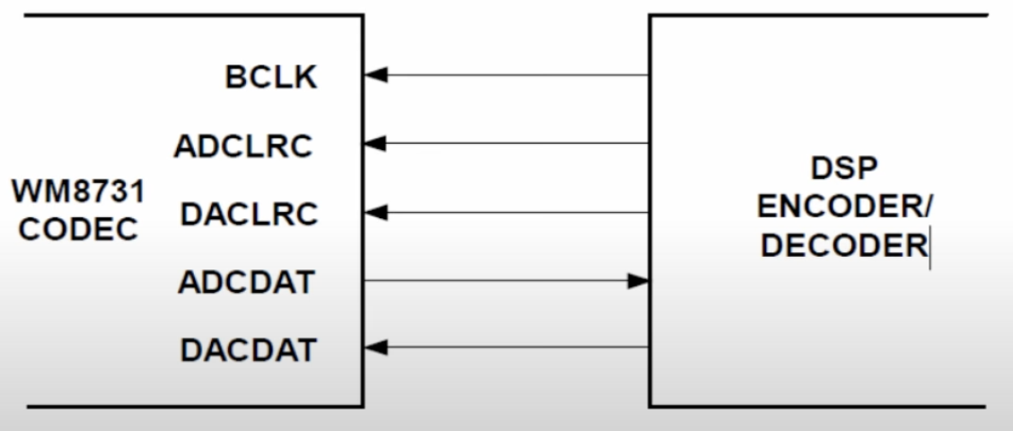
BLCK, DACLRC, DACDAT are provided by FPGA in Slave Mode

- Audio File
The audio file is stored on the on-chip memory, so it has to be preprocessed to be stored there efficiently. We use the Altera IP block for the on-chip memory and the required file format is MIF. To get the file from MP3 to MIF we first converted the file into a 16-bit mono PCM WAV file. After that, we have to strip everything from the file except the actual data, since the PCM data file has all the additional information at the beginning that we don’t need (bitrate, number of channels, file size, etc.). After that we convert the resulting data file into MIF format and its path is added to the Altera IP block.
Software
Software Structure:
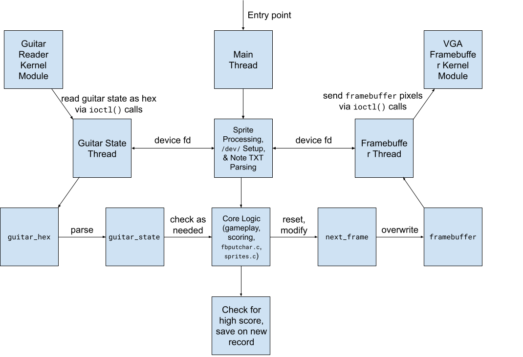
game_logic.c
The most important file. This is the orchestrator that coordinates the input and output. First, the main thread processes the sprites, connects to our HW kernel modules, and parses the hard-coded notes for the level from a .txt file. The game then steps into a start screen menu, then the main gameplay loop, and finally an ending screen that checks for a high score.
guitar_state.c/h
Defines a struct that represents the state of the guitar, plus helper methods for processing the data from the Verilog module into this struct.
guitar_reader.c/h
An adapted version of the lab 3 VGA ball kernel module that communicates with our Verilog module for the guitar.
vga_framebuffer.c/h
An adapted version of the lab 3 VGA ball kernel module that communicates with our Verilog module for the VGA framebuffer.
sprites.c/h
Structs and helper methods to parse, store, and render a sprite from a PNG.
fbputchar.c/h
An adapted version of the lab 2 fbputchar code that works with our custom framebuffer and color palette.
colors.c/h
Defines structs and an enum for representing colors in our color palette.
generate_verilog_colors.py
A helper script that parses our color palette from colors.c and outputs the body of the Verilog switch statement used as a pixel_data LUT in vga_framebuffer.sv.
vga_emulator.c/h
Uses libsdl2-dev to emulate the VGA. Also uses the keyboard to emulate the guitar.
global_consts.h
Defines global constants about the VGA screen output.
song_data.h
Defines constants about the song, such as BPM and notes per measure. Also defines a struct to represent a note of rows on screen.
helpers.c/h
Defines miscellaneous helper methods.
high_score.txt
Stores the highest score (accuracy) a player has achieved on this level.
single_note_commaless.txt
A cleaned export of the CSV for our song, containing information about the notes in every row. game_logic.c automatically parses this file and plays those notes in the level.
Makefile
Defines two important targets: make all, which compiles all the files necessary to run game_logic, and make modules, which compiles all the kernel modules.
Custom Development Tools
Throughout this project, we also developed some custom tools to expedite or automate parts of the development process. For example, the generate_verilog_colors.py tool made it very easy to keep our color palettes synchronized across C and Verilog. When campus shut down, we also took the time to develop an emulation system in C using libsdl2-dev. Dan programmed a system that used the game_logic’s framebuffer in a SDL2 window to render the graphics, which allowed us to continue to develop sprite rendering without our FPGA or monitor. The system also uses the keyboard in place of the guitar, using the keys 1-5 in place of each button on the guitar and the spacebar in place of the strumbar. We were therefore able to develop the graphics and general game logic without physical lab access, and the system was designed robustly enough that, even after all the in-person development we did once campus re-opened, the emulator still worked and the final game can be played entirely in emulation. Just flip int EMULATING_VGA to 1 in the start of game_logic.c to enable emulation.
Results and Performance
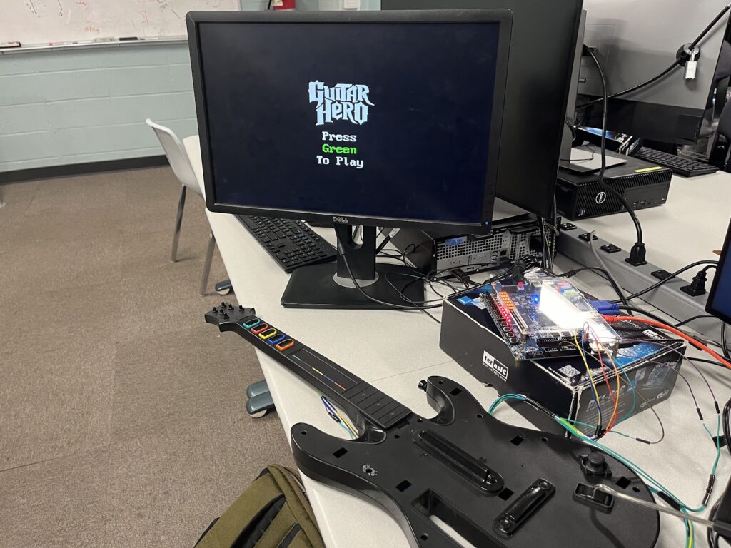
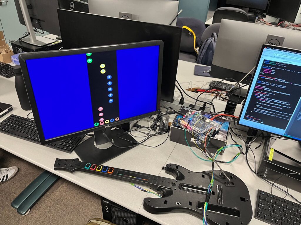
The final results of the game logic, VGA framebuffer, and guitar reader are robust and complete. We even implemented a complete emulation system that allowed us to develop graphics and gameplay without access to the lab — the full game is completely playable in emulation. The scoring algorithm is fairly accurate, but will sometimes fall victim to imperfect strum bar debouncing.
Ultimately, the VGA graphics could use some more optimizations to be smoother. Notably, we could redesign the framebuffer to take in the pixel data for chunks of 5 pixels at a time, and use the address to define the address of the first of these 5 pixels. This way, we could update the contents of the vga_mem module 5 times faster, which might help with smoothness.
The guitar itself could also use some fixing. This guitar is almost 15 years old and underwent several years of use before making its way to this project, and the strumbar was already partially broken (strumming down hardly works), which does notably reduce the rate at which you can comfortably play a rapid series of notes.
The audio part of the project was not successful. The issue was mainly in the fact that we could not set up the wrapper module to work with the other parts of the project (it worked in isolation).
Lessons Learned
Quartus
One of the most important skills we developed over the course of this project is our ability to use Quartus to develop a complete hardware project. Beginning the project, we had a slight introduction to Quartus in lab 3 but had no ability to handle it with agency to create a novel application. What was a learning experience was the need to read documentation slowly and thoroughly to understand how to use the software. After reading Intel user guides that TAs showed us, Quartus became much more manageable and an extremely useful tool.
Memory Efficiency
When writing software on our laptops, we don’t have to concern ourselves with memory efficiency anywhere near the extent to which we needed to in our Verilog modules, where every single bit counted. If we were to do this project again, we’d definitely focus even more on memory efficiency. For example, the VGA framebuffer’s current addressing leaves about ⅓ of its memory unused — a more complex addressing system could probably be designed that would reduce this inefficiency. As mentioned in the previous section, we could also have redesigned how writedata and address are used to have pushed data to the framebuffer 5x faster.
Planning Ahead
Another lesson learned was surrounding planning. Our original block diagram that we submitted for our design proposal lacked a lot of knowledge and research for future steps, especially in communicating with the guitar (which we had not yet obtained). We assumed that each hardware (visuals, controller, and audio) would be relatively simple, but struggled significantly with each. If We were to do a project like this again, we would have spent much more time thinking about what we need to learn before embarking out to build. We chose to build on the fly, and this was fine because the project was of small size, but with a bigger project, the lack of planning definitely would have shot us in the foot.